The historic Gilead Brook Bridge was one of many built following Vermont’s Great Flood of 1927, generally considered one of the worst natural disasters in the state’s history. Three consecutive days of rain in November spawned a deluge that killed 84 people and caused devastating private and public property destruction. Transportation infrastructure was decimated, with more than 1,250 bridges destroyed or severely damaged.
Located approximately 4 miles north of the intersection of VT 12 and VT 107, the Gilead Brook Bridge was unique – a multi-span Warren deck truss bridge. Only four of these were built in the aftermath of the storm. A relatively simple design, a Warren truss configuration produces strength while using less materials, and thus can be lighter and less expensive than other types of trusses subjected to the same design loads. This trait is especially desirable for a long narrow structure located on a steep road such as the segment of VT 12 undergoing bridge construction. The Gilead Brook Bridge is called a deck truss because the road is placed on the top chord of the trusses.
VTrans evaluated several alternative methods for replacing the bridge, including no action, rehabilitation, and complete bridge replacement. The agency determined that strengthening the truss members to meet design loads was not economically feasible. This problem was exacerbated by its age and overall poor condition, prompting VTrans engineers to recommend a complete bridge replacement.
The new bridge is being built a few feet west of the existing structure. The bridges are oriented roughly north-south, with Gilead Brook flowing approximately west to east at this point. Traffic is being maintained on the old bridge during construction of its replacement. Accelerated Bridge Construction methods were not considered practical for this project for a number of reasons: shutting down VT 12 would significantly affect first responders and the traveling public; the new bridge is 38 feet longer and 11 feet wider than the old; VT 12 has a relatively steep slope of about 4.35 percent; and the road is more than 40 feet above the streambed.

| Your local Bomag Americas dealer |
|---|
| WPI |
Also, the substructures and superstructures of the two bridges couldn’t be more different. Two concrete hammerhead piers support the new bridge, compared to three bents each comprised of a pair of concrete obelisks that support the original bridge. Moreover, the new bridge is designed with welded steel girders.
The new three-span VT 12 Bridge has weathering steel plate girder superstructure, and for aesthetic reasons, features parabolic haunched webs at the piers. The frame typically consists of four 66-inch welded steel plate girders spaced 9 feet, 2 inches apart that are braced with crossframes. Weathering steel meets AASHTO grade M270 50W, which means the uncoated (or unpainted) steel exhibits higher resistance to atmospheric corrosion than other steels, because it forms its own thin protective surface layer that regenerates continuously when subjected to weather. In other words, the steel is allowed to rust in order to form the protective coating.
The new bridge is 364 feet long including two approach spans of 110 feet and a center span of 144 feet. Its 35-foot fascia-to-fascia width provides ample space for two 11-foot travel lanes; two 4-foot, 10-inch shoulders; and galvanized steel guardrails. An 8-1/2-inch-thick high-performance concrete deck – designed to be more durable and stronger than conventional concrete – is topped with a 3-inch bituminous concrete pavement to complete the roadway.
In a move that recalls the Gilead Brook Bridge listing on the National Register of Historic Places, VTrans specified the addition of an ornamental steel lattice railing similar to that of the original bridge. Composed of crisscrossing 2x¼ steel bar stock and L3x2x¼ angles, the lattice is attached to the outside face of the highway guardrail.
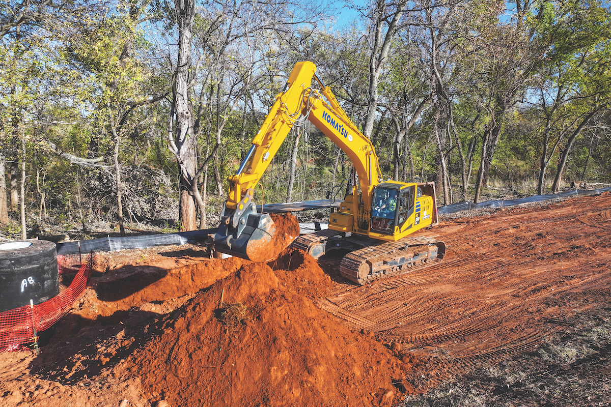
Almost immediately after the contract was awarded, the contractor began work to restore a large portion of the northwest embankment of the original bridge, which had been washed out by a recent heavy storm. St. Onge fielded a number of heavy construction equipment pieces for the earthmoving, among them: two Caterpillar off-road trucks, three excavators (Caterpillar 320, 330 and 345), and a Caterpillar 928 Loader. This effort included bringing in to the site some 2,500 cubic yards of riprap and soil. In line with earthwork, project specifications call for the contractor to manage its construction activities to limit earth disturbance to 2 acres or less at any given time, while adhering to a construction sequence proposed in the documents. This requires precise control of earthmoving operations.

| Your local Wirtgen America dealer |
|---|
| Kirby-Smith Machinery |
Major structural work began with Pier #2, the northern one of two support substructures that tower some 40 feet above the streambed. Located near the edges of the existing brook channel, the piers have 8-foot-diameter columns and 34-feet-wide by 8-foot, 6-inch caps. Pier construction was facilitated by the use of EFCO concrete forms for the columns and caps. Each pier is set on a 5-foot-deep, 26-foot by 26-foot concrete footing. Carroll Concrete supplied about 1,150 cubic yards of high-performance concrete for all substructures and superstructures, with an estimated 192,000 pounds of rebar provided by Dimension Fabricators Inc.
Following Pier #2 construction, crews built Abutment #2, and wingwalls. Then, proceeding southward, they built Pier #1, Abutment #1 and its wingwalls. The 34-foot-wide by 13-foot-deep abutments are supported by HP 12x84 steel piling embedded at least 2 feet into the concrete. With concrete substructures completed, the contractor prepared to erect bridge girders.
Casco Bay Steel Structures supplied approximately 215 tons of weathering steel and about 350 linear feet of steel pilings for this phase of the work.
Project Manager Richardson indicated the job has progressed very well towards a fall 2020 completion.
“We started this job in June 2019, and we had already built the piers and abutments and set the steel by the week before Christmas,” he said.

| Your local Wirtgen America dealer |
|---|
| Kirby-Smith Machinery |


