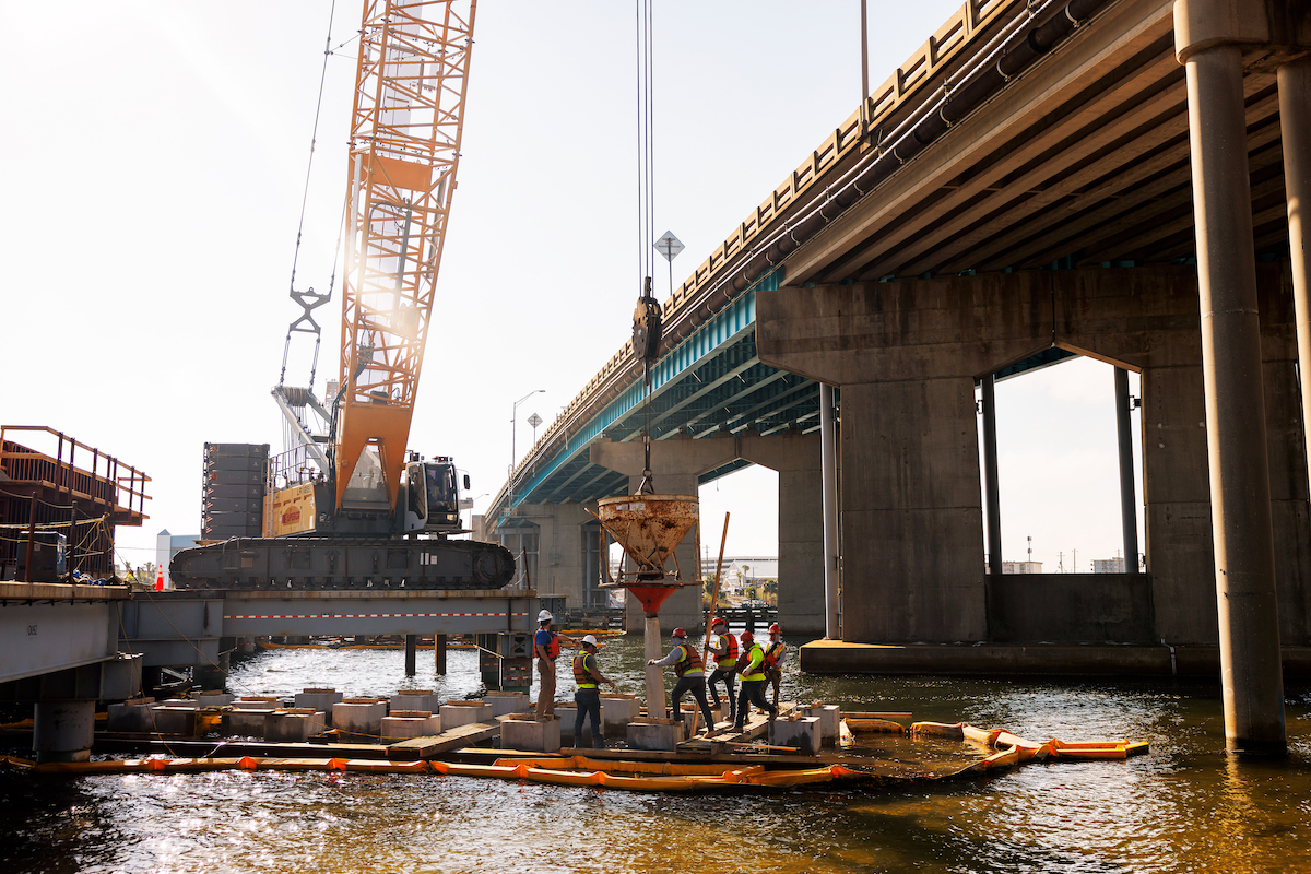
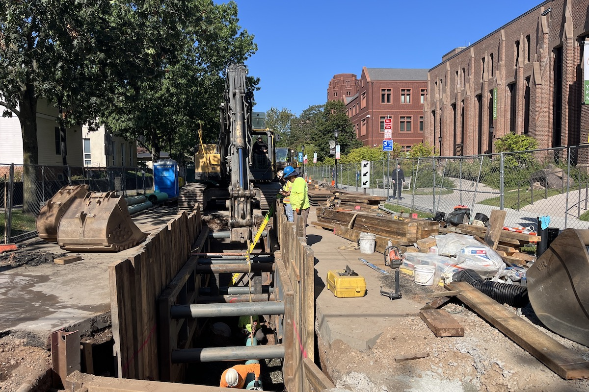
Empire Paving Inc. (EPI) of North Haven, Connecticut, has a $2.9 million contract with the City to build the Harbor Brook Overflow Culvert near Amtrak Bridge MP18. Two sets of Amtrak tracks pass through the middle of this community and over the 120-year-old bridge. Owing to its deep plate-girder construction, the old structure provides only limited clearance above Harbor Brook, presenting an obstacle to stormwater flows. The City has spent more than $20 million in flood control work over the years, including the current EPI contract, to rectify the problem.
“The culvert will carry overflow from Harbor Brook under the embankment that carries two active Amtrak railroad tracks, and discharge the overflow back to the Brook downstream of the Amtrak bridge. The pipes in the bypass culvert upstream of the bridge are being installed by the trenchless jacking method, with the jacking pit located in the adjoining parking lot, while conventional open-cut methods are used for the remaining culvert. Employing pipe jacking allows the continuous use of the railroad tracks during construction.”
AECOM called for the following installations: two high-density polyethylene (HDPE) pipe overflow culverts from upstream of the Amtrak Bridge at Harbor Brook to a point downstream of the bridge; steel casing pipes jacked under the Amtrak Railroad and grouting in place; HDPE water carrier pipes sleeved within the steel casing pipes and grouting in place; a concrete junction chamber; and construction of headwalls plus reconstruction of the parking lot in which the pipe culvert and jacking pit are located.
The HDPE carrier pipe have smooth 60-inch inside diameter and 67-inch corrugated outside diameter. Set 9 feet center-to-center, each carrier pipe is installed in a permanent 73.5-inch outside diameter steel casing pipe. The two 50-foot-long steel casings, comprised of joined 10-foot lengths, have a 3-foot clear distance between them, and are oriented at a 60-degree skew to the railroad track alignment.

| Your local Bomag Americas dealer |
|---|
| Linder Industrial Machinery |
Zwicharowski said that EPI is self-performing most of the work such as driving steel sheeting and soldier piles, installing open cut pipe, dewatering where necessary, placing ready mix concrete, and performing site excavation, grading and paving. The pipe jacking was subcontracted to CRS Contractors – formerly Cruz Contractors – of Colts Neck, New Jersey.
While digging the jacking pit, EPI crews realized that the actual elevation of one of the existing walls differed from that shown on project plans, requiring a support-of-excavation system to be set up.
“We contracted Seifert and Associates of Naugatuck, Connecticut, to design a system to permanently support the stone wall,” he said. “This came with complications since ledge was not far below the bottom of excavation, limiting the amount of toe we were able to achieve on the steel sheeting.”
Another difficulty presented itself when some contaminated water was encountered. “We immediately contacted Recon Outfitters of Sturbridge, Massachusetts, and they came and solved the problem with a mobile water treatment system,” Zwicharowski said.
“After we dug the jacking pit and installed the earth support system, CRS set up to jack the two steel casings, which would be followed by insertion of 60-inch Sanitite Polypropylene Pipes manufactured by Advanced Drainage Systems. The pipes were supplied by Ferguson Waterworks of Newington, Connecticut,” he said. He indicated that jacking is taking place one casing at a time, and that it is a difficult procedure calling for crews to work around the clock.

| Your local Gomaco dealer |
|---|
| Ring Power Corporation |
“In addition, before jacking could take place, we had to install a continuous remote settlement monitoring system. This involved mounting over 40 prisms on the train tracks and soil over the proposed pipeline. The system is supplied, operated and installed by Freeman Associates of Hartford,” he pointed out.
Crews also needed to be ready to improve the stability of soft or unraveling soil if encountered. By working closely with Avanti International, the construction team was able to select a grout to improve soils stability that could be applied by injecting the earth face from inside the tunnel. They also sought and found a way to excavate soil within the tunnel that was superior to conventional mechanical or hand digging. CRS contracted Badger Daylight to employ Hydrovacs to excavate the earth. Badger Hydrovac trucks use highly pressurized water to liquefy the soil, creating a slurry type mixture. Simultaneously, this mixture is extracted by the Badger vacuum system into a truck-mounted debris tank.
PJA notes that to install a pipeline using this technique, thrust (jacking) and reception pits are constructed. A concrete thrust wall is often constructed in the pit to provide a reaction against which to jack, or a structural framework such as piles, ground anchors or other methods for transferring horizontal loads can be built. To ensure that the jacking forces are distributed around the circumference of a pipe being jacked, a thrust ring or a jacking frame is used to transfer the loads. The jacks are interconnected hydraulically to ensure that the thrust from each is the same. Furthermore, a reception pit for removal of the jacking shield is normally required at the completed end of each drive. The initial alignment of the pipe jack is obtained by accurately positioning guide rails within the thrust pit on which the pipes are laid. To maintain accuracy of alignment during pipe jacking, it is necessary to use a steerable shield.
As the pipe advances, the encapsulated soil is removed by the Badger Hydrovac. Four hydraulic jacks inside the steering shield are operated to keep the pipe on line and grade as the jacking frame’s larger jacks push the assembly forward. At the end of the 10-foot drive, the jacking frame is backed off to allow the placement of the next length of pipe, then the procedure is repeated.
Once jacking has been completed, the carrier pipes will be inserted inside the casings, and the annular space between the pipes and the walls will be grouted for watertight seal. A 50-ton precast concrete junction chamber supplied by United Concrete of Yalesville, Connecticut, will be installed inside the jacking pit. In operation, this structure will direct overflow from the carrier pipes within the casings, to twin 60-inch carrier pipes previously installed by EPI using open-cut-and-cover means. This essentially completes the bypass culvert loop to the outlet at the downstream end of the Brook. There is still plenty of work to be done, but the job is on schedule, according to Zwicharowski.

| Your local Wirtgen America dealer |
|---|
| Beard Equipment Co - AL |
| Tractor & Equipment |


