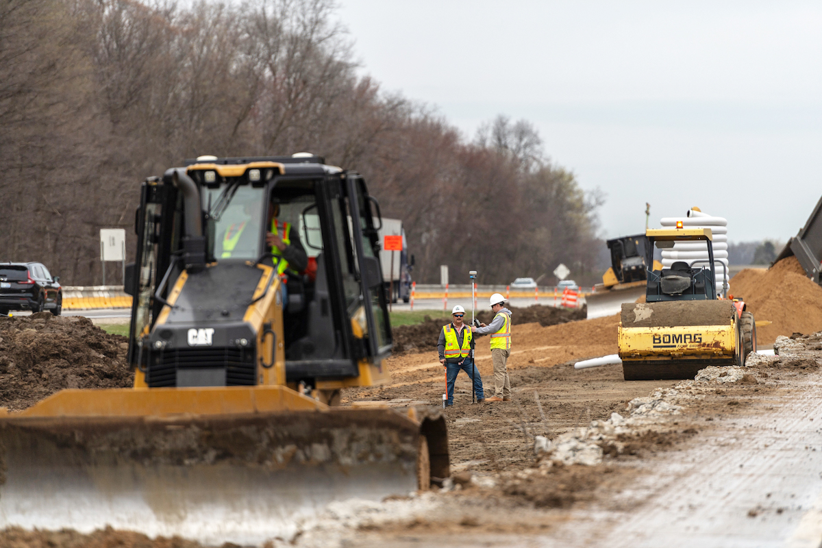
“This has been one of our more demanding projects,” said John Bousquet, Project Manager and Vice President of the Plymouth, New Hampshire, company. “The most challenging part has been working in tight spaces that have to be shared with moving traffic, while shifting our focus from one phase of the job to another,” said the 35-year construction veteran.
Bidding was tight for this New Hampshire Department of Transportation (NHDOT) project, with the lowest three bids within 3.4 percent of one another, and the lowest and second lowest bidders within just one percent of each other.
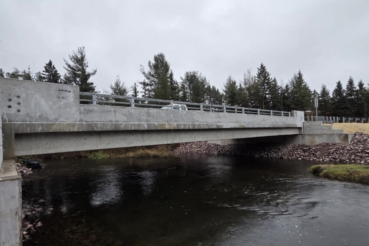
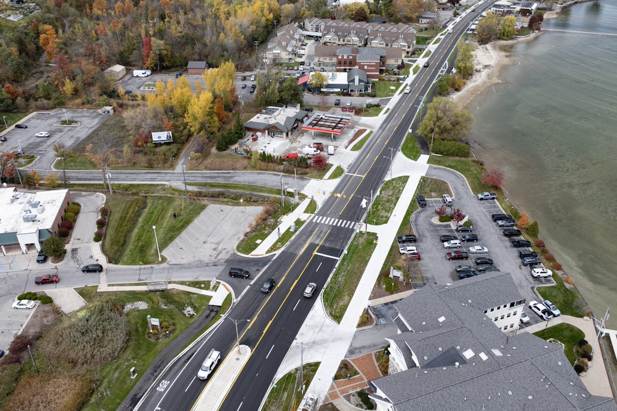
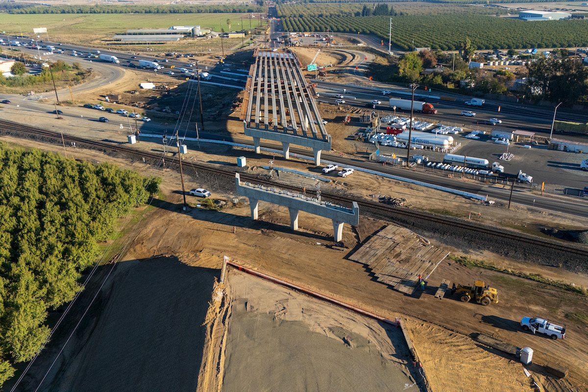
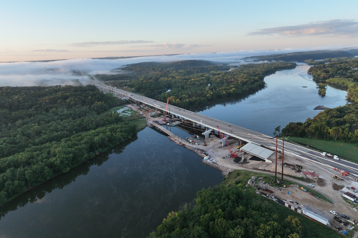
Piper won the challenging $3.3 million contract to replace NHDOT’s Bridge 158/137, which carries U.S. 302 over the Lake Conway Outlet. Built in 1955, the existing bridge is currently on the state’s Red List because of its declining deck, superstructure, and substructure. NHDOT describes a Red List bridge as one that is structurally deficient, based on one or more of these major bridge elements being in poor or even worse condition. As part of the State's 10-Year Transportation Improvement Plan, the project involves not only the bridge, but about 1,500 feet of U.S. 302. The approach roadway is designed with full box construction on a new, northerly shifted alignment.
Stream crossing design has become increasingly important in light of today’s emphasis on environmental protection. Strict state regulations direct that the channel design of new crossings or modifications of existing crossings conform as much as possible to the natural stream in both physical structure and function. This preserves the natural alignment of the stream while minimizing potential for obstruction by sediment, wood and debris. Furthermore, channel crossings must provide adequate hydraulic capacity, water depths and velocities similar to those upstream and downstream, and maintain sufficient water depths during occasions of low flow. The Conway crossing has been designed to handle flows from a 100-year storm.

| Your local Trimble Construction Division dealer |
|---|
| SITECH Michigan |
“Bridge work will be completed in three construction seasons. The existing bridge will carry both directions of traffic in Phase 1 while the new bridge is partially constructed. Phase 2 will carry eastbound traffic on the existing bridge while westbound traffic is carried on the new structure and Phase 3 will carry both directions of traffic on the new bridge...” said NHDOT Commissioner Sheehan, who holds a Masters Degree in Structural Engineering and Architecture and heads a state agency with than 1600 employees and an annual operating budget of about $650 million.
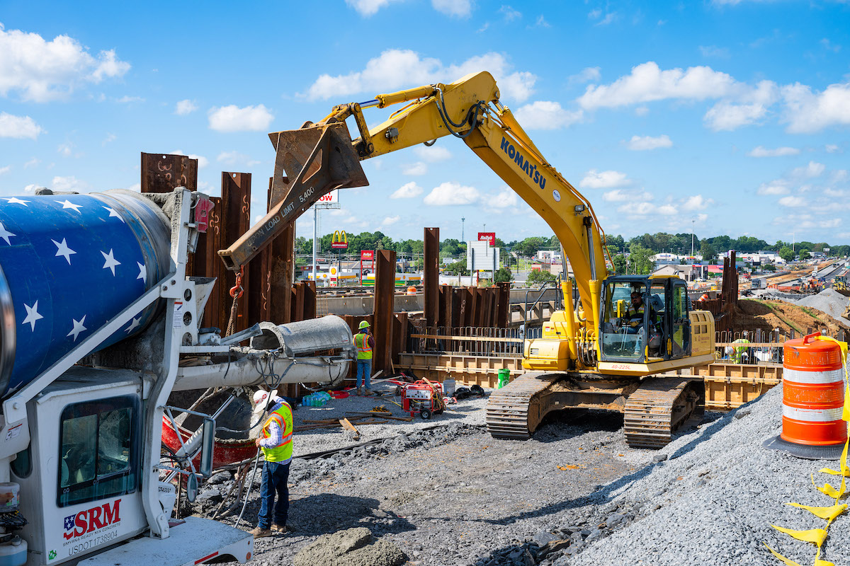
The bridge substructure consists of reinforced concrete integral stub abutments on steel piles. Seven HP12x63 piles were driven for each abutment by subcontractor Leslie E. Roberts, LLC. The piles are centered beneath the seven girder bearing pads on each abutment’s bridge seat. Roberts was also responsible for driving sheetpile for several cofferdams that were built as a safety precaution to separate excavation work areas from adjacent traffic.
Arc Enterprises fabricated the seven, 120-foot-long plate girders for the bridge frame. The girders were fabricated with 1/2-inch thick webs averaging 45-1/2-inches deep. Each 120-foot girder was shipped from the factory to the jobsite on a single tractor-trailer.
The seven continuous girders are connected by 36 cross-frames (sometimes referred to as diaphragms). These structures are fabricated of 3-1/2 by 3-1/2 by 1/2-inch angles and are installed between adjacent girders every 22 feet. As key structural members, cross-frames resist torsional forces and are used to transfer and distribute vertical and lateral loads, providing stability to the girder compression flanges. Six of the cross-frames are modified to assist in the placement of girders during steel erection.
In Phase 2, an additional 8 feet of the old bridge is demolished and the Clampcrete barrier is relocated to the new edge of the narrower bridge, allowing one eastbound lane of traffic. Meanwhile, an additional girder (5) is added to the new bridge. This is where the modified cross-frames help steel erection by allowing girder 5 to be connected to girder 4, which is stabilized by the weight of the previously constructed partial deck. An additional 6 feet, 6 inches of bridge deck and pavement are constructed over girder 5. The widened new bridge is now capable of carrying one lane of westbound traffic.

| Your local Deere & Co dealer |
|---|
| AIS Construction Equipment |
In Phase 3, girders 6 and 7 are hoisted in place on the abutments, with the help of the modified cross frames that allow girder 6 to be connected to girder 5, which is stabilized by the previously constructed partial deck. The full-width bridge deck and pavement are completed, and the new bridge carries both lanes of traffic, while the remainder of the old bridge is demolished.
Coleman Concrete, Inc. is providing ready mix concrete. Barrier membrane was provided by A.D. Rossi. Another subcontractor, CWS Fence and Guardrail, is installing both bridge rail and roadway guard rail.
Burke Quarry LLC supplied the aggregates for the project while Continental Paving Inc. has supplied and installed bituminous concrete.
There is considerable ancillary work related to the main tasks that involves removing roadway pavement on the old alignment, removing and installing guardrail, installing drainage, constructing a water treatment swale and shaping roadway slopes. The contractor is also armoring the Conway Lake Outlet river banks through the proposed bridge to match existing stone rip-rap remaining in place. Subcontractor Continental Paving is paving the roadway approaches and two drives on the approaches.


